Mounting example type 5 special - Door and wall mounting on gateposts with centrally located door hinges

I. Check material and tool list
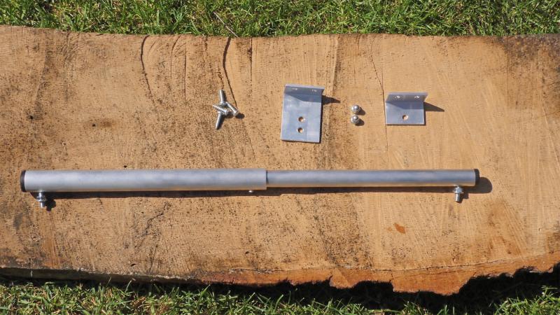
Your garden gate closer is delivered already assembled. Your product also includes two aluminium brackets with different side lengths, 4 tapping screws and 2 cap nuts.
WARNING: The garden gate closer is preloaded! The preloading safety should not be removed before insertion! Due to preloading the threaded rods of the gate closer are skewed. They will adjust during assembly.
- 1 garden gate closer
- 1 aluminium bracket (bracket 1): 60, 90 or 120 mm
- 1 aluminium bracket (bracket 2): 30 mm
- 2 cap nuts M6
- 4 tapping screws 4,8 x 19 mm
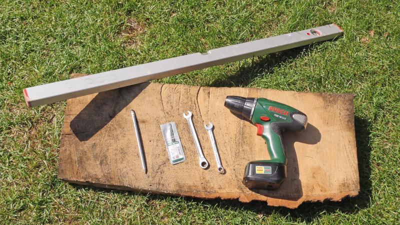
You will need a cordless screwdriver with a 4.2 mm and a 6 mm metal drill and a cross slot (Phillips) screwdriver (PH2) for installation. Furthermore, you need a spirit level, measuring tape, pen and two no.10 fork wrenches as well as an impact drill, and suitable dowels and screws for your type of masonry, a cone drill and a 10 mm socket wrench.
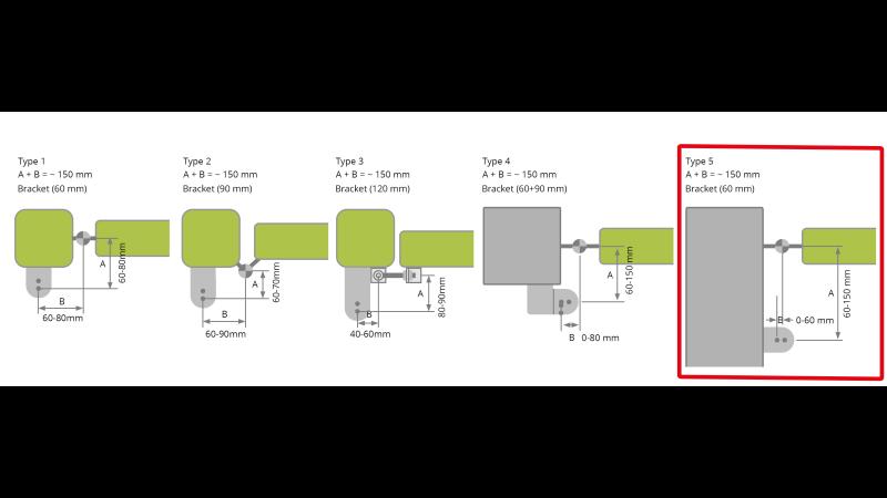
II. Determine type of mounting
The following mounting example shows a special mounting situation of mounting type 5, that is the mounting on gates with door hinges installed at the wall. In this special variant, the gate closer will not be installed with the enclosed bracket 2 but directly onto the gate. In our specific measures we use bracket 1 size 60 mm. For different situations, you may eventually need a longer (90 or 120 mm) bracket. All available mounting brackets can be found in the category Accessoiers.
III. 6 steps for successful mounting
- Determine mounting position of gate closer
- Measure bracket 1
- Check piston stroke
- Mount bracket 1
- Determine mounting position on gate and prepare gate
- Insert and tighten garden gate closer
Step 1: Determine mounting position of garden gate closer
First, you need to determine the position of the gate closer. It can be positioned at the top of the gate, in the middle or at the bottom. It is important that it is mounted levelled! As well, the two brackets (bracket 1 and bracket 2) need to find sufficient hold on the wall and on the gate respectively. The larger bracket (bracket 1) is to be mounted on the post. The smaller bracket (bracket 2) won´t be used in this special mounting variant!

Step 2: Measure bracket 1 wall-sided
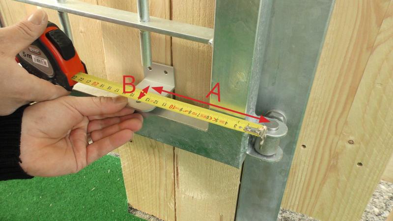
After having positioned the gate closer correctly, check the distance of the gate´s pivot point (located in the middle of the hinges) and the pivot point of the closer (chosen mounting hole of bracket 1). For measuring use the larger bracket (bracket 1).
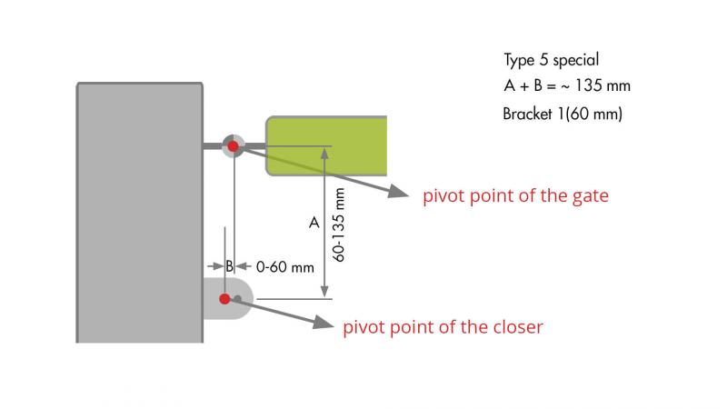
The sum of the two distances A and B in this special case should not exceed 135 mm, and also should not be less than 125 mm either. However, if the sum of the distances is bigger than 135 mm, the gate can only be opened a little less than 90° at worst.
In this special case, distance B can be „0“. Consequently bracket 1 will be mounted in such a fashion, that the distance of the mounting hole of bracket 1 and the centre of the hinges amounts to 135 mm (see plan: A = 135 mm, B = 0 mm).
Note: In step 3 the exact positioning of the bracket will be checked again and possibly fine-tuned.
Step 3: Check piston stroke
This step is to check the measured position of bracket 1 and possibly change it slightly, so that the optimized closing performance can be guaranteed. If you choose to proceed with the measurements done before you can skip this step. However, we strongly advise you to take your time for this verification.
To verify the mounting positions fix bracket 1 provisionally at the position as measured before and install the gate closer in the mounting hole as chosen before. Close the gate and mark the position of the bolt on the frame of the gate (mark 1). Then open the gate and mark again the position of the bolt on the frame (mark 2).
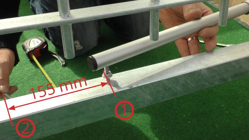
If the distance between the two marks amounts to about 155 mm, the position of the bracket is optimal. If the distance is a bit less, increase distance B a bit. If the distance is bigger than 155 mm, decrease distance B or choose another mounting hole.
Note: The gate closer can be installed in any mounting hole of the bracket, as long as the distance is correct. If you use a larger bracket than 60 mm (90 or 120 mm) we advise you to choose one of the centred mounting holes so you can possibly fine-tune the gate closer later.
Step 4: Mount bracket 1
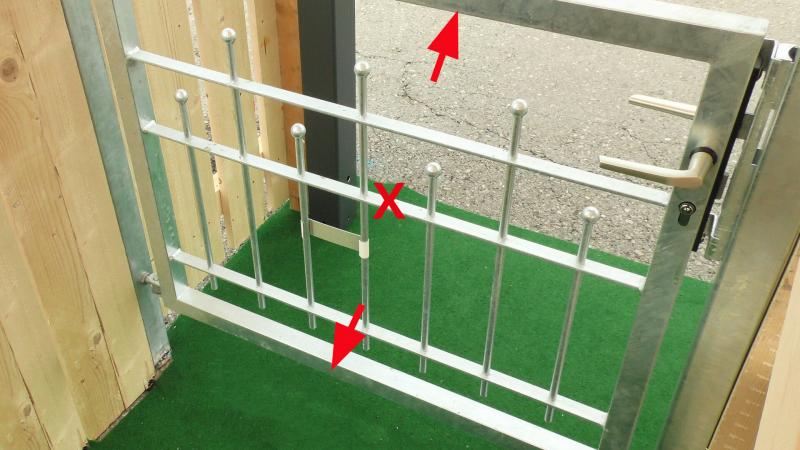
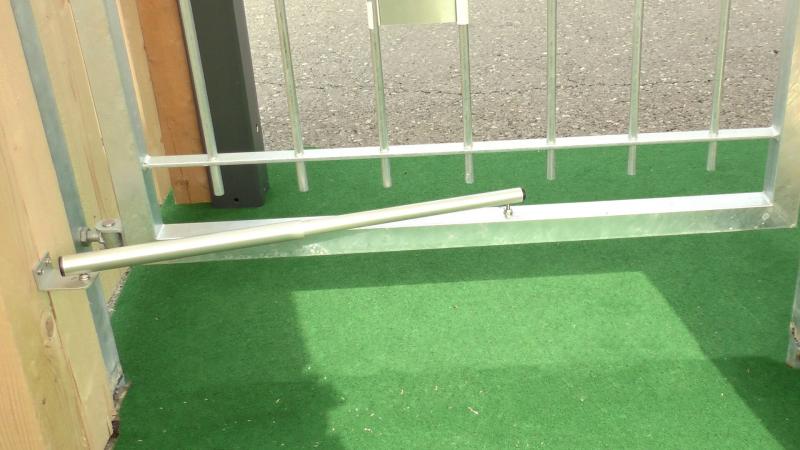
If like in this example, the distance between the open gate and the wall is practically zero, we advise you to position the gate closer plus bracket in-between the decorative elements of the gate (see picture). The reason for this is, that if the open gate touches the bracket or the closer, it cannot be opened fully (90°). In case that it is not possible to mount the closer in-between the gate elements, you can also mount it above the gate so that the full opening is guaranteed.
In our example, the position of the bracket is also measured vertically, so that the bracket plus closer and cap nuts fit in-between the decorative elements of the gate.
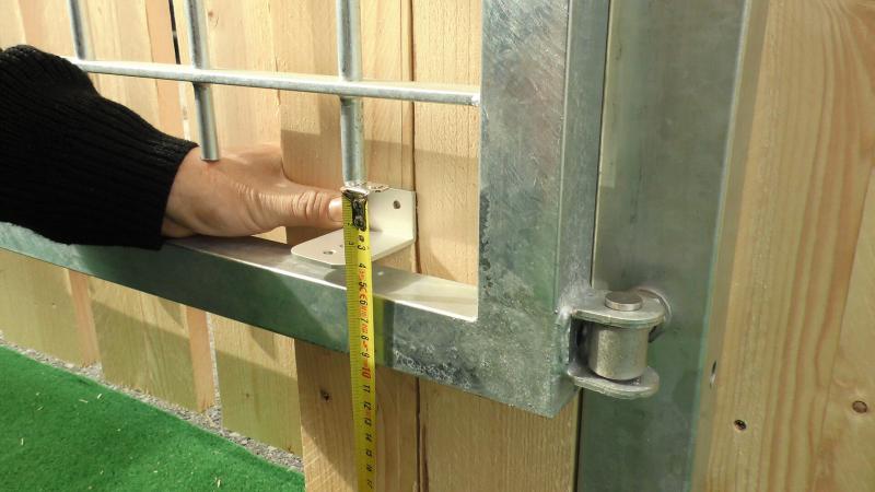
After having measured the correct position of bracket 1, fix it using suitable mounting material (e.g. screws or dowels and screws). In our example the two screws enclosed are sufficient.
Attention: Make sure that the bracket lies flat upon the wall. In the case of brick or stone walls, level the ground before mounting!
Step 5: Determine mounting position on gate and prepare gate
Having positioned and fixed the first bracket (bracket 1) correctly, you´ve already done the biggest part of the mounting!
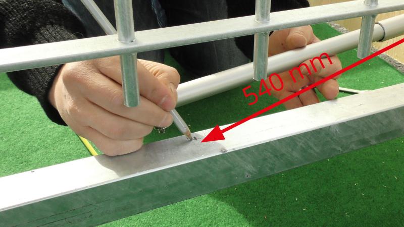
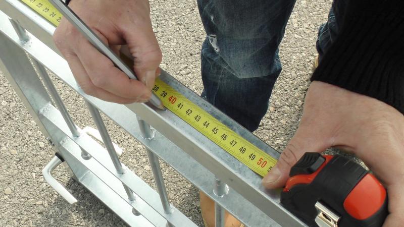
Now, the mounting position of the closer on the gate will be determined. Remember: The second bracket (bracket 2) will not be used, because the closer will be installed directly on the gate. The distance between the mounting hole on bracket 1 and the mounting hole of the closer on the door must be between 540 mm and 545 mm. Exact measurement is essential here!
As an alternative you can remove the preloading savety pin and measure the necessary distance at site. Do not forget to subtract 10 mm for preloading. But be careful: If this distance is too small, the gate will only open a little less than 90°. If it is too big, the gate won´t close entirely.
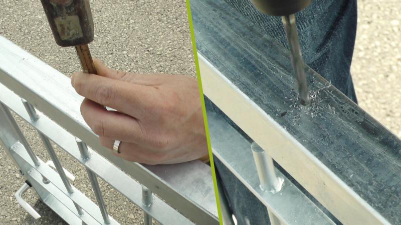
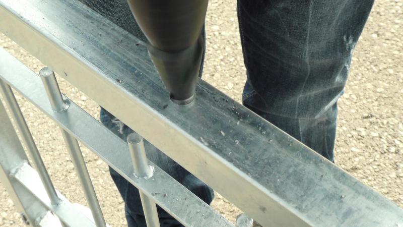
Having measured the distance correctly, unhook the gate and transfer the mounting position to the bottom of the frame. Then drill the frame entirely using a 6 mm metal drill. Make sure that the drilling is done straight in line. As a next step, widen the drilling hole at the bottom up to 12 – 14 mm using a cone drill. This is necessary, so that the 10 mm socket wrench can be placed.
Attention: If you adjust the position of bracket 1 later, the mounting hole on the gate must be re-positioned as well to ensure the correct hole-to-hole distance.
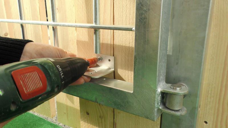
Step 6: Insert and tighten garden gate closer
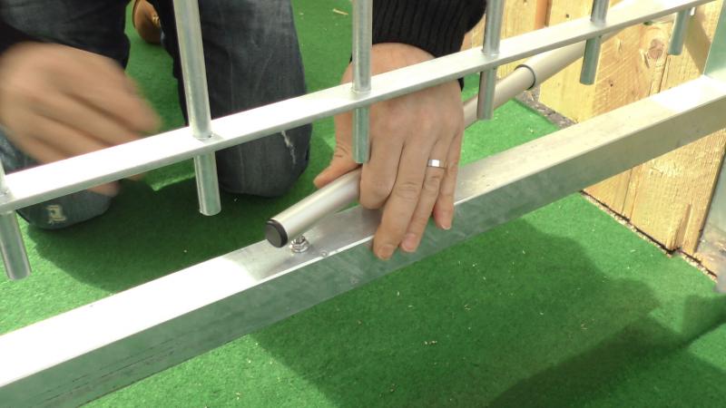
Now, put the gate back to its original position. For mounting the gate closer the thicker end of the closer must be put into bracket 1. The slimmer end must be mounted into the drilling as done in step 5.
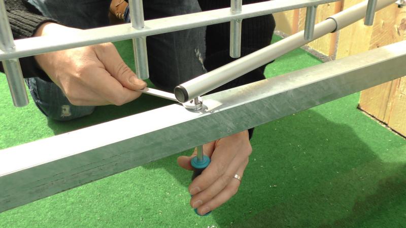
Finally, the gate closer is fixed using the cap nuts. Therefore screw on and tighten the cap nuts using the locknuts. In this step the nuts have to be tightened in such a fashion, so that the threaded rods are straightened and stand in right angles to the mounting bracket or the gate respectively.
Note: In most cases, the pre-loading security bolt loosens by itself during this procedure. In case that the bolt remains, carefully move the gate just a few millimetres towards its opening direction!
You’ve done it. We hope you enjoy your new Garden Gate Closer!
If you have any further questions about the assembly, do not hesitate to contact us via email office@gardengatecloser.com or via our WhatsApp service +43 664 881 89 781!
Your gardengatecloser.com team